


Hardware

- XI35Pro frame(O3 Version) kit includes almost most parts you need to assemble one complete drone. So you don't need to buy an extra screw set or aluminum column or printed parts.
- Here we use the Spinnybois 2006 2150kv(6s) motors that are specially designed for XI35Pro frame. The motors not only provide strong power but also silky smooth videos. With 6s 1300mah 120c battery, XI35Pro O3 version can get up to 12min flight time.
- ODDITYRC F7 AIO can provide 6 UART ports and enough current, also the STM32F722 chip provides enough computing power. You can use any AIO that supports 6S voltage and at least 35A current.
Tools Required
-
Soldering iron
-
1.5mm and 2mm hex drivers
-
Precision Tweezers
-
Scissors
-
Ruler and cutting mat
-
Multimeter
Additional Supplies
-
5mm wide motor wire organizers
-
Zip ties (small)
-
63/37 leaded solder
-
Liquid soldering flux pen
Frame Assembly
| Part Number | Corresponding Model |
| 1 | M3 x 14mm screw |
| 2 | M3 x 6mm screw |
| 3 | M2 x10mm self tapping screw |
| 4 | M2 x 12mm screw |
| 5 | M2 x 8mm screw |
| 6 | M2 nut |
| 7 | M2 locknut |
| 8 | M2 x 10mm screw |
-
Install the battery strap first because it's almost impossible to make it pass through the holes after mounting the AIO.
-
The side of the plate with logo is top side. Install the 7 aluminum columns with corresponding screws listed in the form above. Don't forget to refer to the picture below first to install print parts (O3 camera mount and dual antenna mount) .


Mount the Flight Controller
- Insert the dampeners into the holes around the board. A neat trick is to wrap dental floss around one end to pull it through the hole.
- To mount the flight controller, use the included 10mm M2 screws. Pass the 10mm screws through the 25.5mm holes on the top plate. Slide the board onto the screws and secure it with the included M2 locknuts.
- The aio board is recommended to mount in this direction, which is much easier to solder wires. But in this way gyro direction and motor numbers are changed. It's okay we can set them in Betaflight later.
- Be careful with the tightness of the M2 nut and make sure there is enough space for the damper to deform.


Motors
- To mount the motors use the included 6mm M2 screws. The included screws all have blue Loctite on them, so you don't need to add extra. Pull the wires tight and fix them to the arms with 5mm wide wire organizers.
Here's my soldering process:
-
Flux and add a small drop of solder to each motor pad. It should be just enough to cover all the copper.
-
Cut each wire to length as you go. Be very careful not to cut them too short.
-
Tin each wire end before soldering.
-
Carefully and lightly tap the tinned wire onto the pad.
Solder and Bind the Receiver
Here we're using a Radiomaster TX12MKII with TBS Micro TX and TBS nano RX receiver. You'll need to refer to the flight controller documentation to learn how to wire a different radio and receiver. This can be found on the product page linked above. You need to solder the 4 wires to the receiver and then connect it to AIO.
Receiver TX--->FC RX1
Receriver RX--->FC TX1
Receiver 5V--->FC 5V
Receiver GND--->FC GND

Bind process:
-
The TBS Nano goes into bind mode automatically so you don't need to press the button. If it was previously bound you can press the button or wait 1 minute for it to go into bind mode.
-
Make sure your Crossfire transmitter is configured to the correct frequency, 915 MHz in the US, and your Max Power is set.
- Turn your radio on and put it into bind mode and power up your quad with a lipo battery.
- The radio should indicate a successful bind and it may request a firmware update for the receiver. Let that complete.
- Unplug the battery and plug it back in to make sure you've got a bind (green light).
Video Transmitter
- If you're using Crossfire you can exclude the SBUS and Ground pads. Plug the included O3 cable directly into the AIO airunit socket. They'll need to wrap under the air unit from the very back all the way to the front of the flight controller.
Mounting the O3 air unit and camera:
-
Get 4 M2x20mm screws and pass them through the bottom plate. Use 2 M2 plastic washers to give the air unit some space below.

-
Slide the air unit down over the 20mm screws and secure it with M2 nuts.
-
Plug the air unit into the flight controller and carefully twist and fold the wires so they don't hang off the side.
-
Use 2 M2x4mm screws to secure the camera to the camera mount. Adjust the camera angle as you wish.
Finishing Up
Now let's take care of all the finishing touches. This should cover everything except the propellers. You don't want to put those on until everything is fully configured and tested in Betaflight.
-
Add the standoffs to the front of the frame.
-
If you're using Crossfire mount it to the GPS holder.
-
Take off one of the antenna caps and slide the antenna through the holder. Put the cap back on.
-
Send the antenna cable through the top plate.
-
Put some shrink tube on the receiver and connect the antenna.
-
-
Use some small sharp point screws to secure the antenna holder to the GPS mount.
-
If your screws are too long you can flip the antenna holder over so the screw-wells point downward.
-
-
Use a small zip-tie to fix the receiver on the tail fork.
-
Add a sticky battery pad.
Betaflight Setup
Now let's hop on over to our computer and configure the flight controller. Download Betaflight Configurator Download. Use a Micro-USB cable to plug your quad into your computer.
Flash the Firmware
The newest stable version of firmware optimizes ICM42688P gyro much better than previous versions so it's recommended to update the firmware first.
-
Go to the Firmware Flasher and choose "Release", "ODDITYRCF7AIO" and the latest stable release of Betaflight (newest stable version) and leave the remaining options default.
-
Click "Load Firmware [Online]" and then "Flash Firmware" to update your flight controller. Once complete, click "Connect"

Based on firmware , ODDITYRC F7 AIO and Spinnybois 2006 2150kv motors, we've tuned a preset for it. You can download the preset here and load the txt file in Presets tab--->Load backup.
The preset includes everything you need to tune except modes.
If you want to set by yourself step by step, follow the next instructions.
Configuration Tab
-
Under System configuration, set PID loop frequency to 8kHz.
-
Under Personalization, set your FPV craft name and pilot name.
-
Under Arming, set the Max arm angle to 180 (Only if you keep the accelerometer turned on)
-
Under Boards and Sensor Alignment, set Gyro CW90°, other setups remain default.

-
Under Configuration--->Dshot Beacon Configuration enable "RX_SET" and change your beacon tone to 1.
-
Under Other Features enable: Airmode, OSD.
-
Click Save and Reboot.
PID Tuning Tab
- We've finely tuned the XI35Pro O3 version's PID so it's highly recommended that you download the CLI files directly from our google cloud drive and load it in CLI.
- Download link:
- Important Notice:The PID configuration is based on the premise of perfect installation and same hardware(especially AIO and motors), otherwise may cause unstable flight or motor overheat.
- To complete the remaining steps apply lipo power and turn your radio on, also make sure your props are uninstalled.
DJI O3 Airunit Bind
-
Bind your O3 airunit to your DJI goggles by pressing their respective bind buttons(Make sure the firmware versions of the 2 devices are compatible).
-
Make sure you've got a video link.
Receiver Tab
-
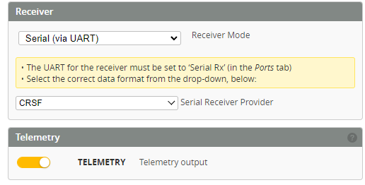
Under Receiver choose your receiver type. If you use Crossfire or ELRS choose "Serial Receiver Provider" and "CRSF" and Telemetry function is suggested to open(Only if you turned on telemetry in the radio control).
-
Ensure your pitch, roll, throttle and yaw are being applied correctly. Adjust your Channel Map as needed.
Modes Tab
-
Assign an Aux switch to arm and disarm your quad.
-
Assign another Aux switch to enable Horizon or Angle mode if you need.
-
Assign the Beeper and "Flip over after crash" to a 3rd and/or 4th switch.
-
Click the Save button.
Motors Tab
-
Under ESC/Motor Features select DSHOT600 and enable Bidirectional Dshot(based on Bluejay ESC FW). Be careful with the number of motor poles. If set incorrectly, desync of motors may occur. The amount of the magnets in Spinnybois 2006 is 14, so we set it to 14 poles.
-
Under Mixer set "Motor direction is reversed" if you want to fly "props out". This is what we recommend.

-
You need to change motor resource in CLI before checking the motor rotation direction. Since the AIO is mounted 180° flip, motor 1 and motor 3 are switched, motor 2 and motor 4 are switched. You just need to switch the motors' resources and it will work.
-
Slide the master to around 1040 so you can rub the side of each motor with your finger to determine the rotation.
-
Refer to the image on top and take note of any that needs to be reversed.
-
You might also want to ensure each motor is in the correct position by referring to the numbers in the image and powering them one by one.
-
If any motors need to be reversed, continue on to esc-configurator.
OSD Tab

On the OSD tab,check all of the values you want and arrange your OSD as desired. These are the values we recommend.
-
Battery average cell voltage and total voltage
-
Link quality and Rssi dBm value
-
Throttle position
-
Timer
Bluejay ESC firmware setup
- The Bluejay firmware uses a very convenient browser-based configurator. You only need to enter the URL in Chrome browser: https://esc-configurator.com/
- Connect the AIO to your PC, choose the right port and click Connect bottom.

- Click read settings and the page will show the current settings of ESCs.Then click Flash all ESCs.

- Choose Bluejay, ESC type stay default, latest Version(V0.19.2) and 48K PWM Frequency.
- It is not recommended to set PWM Frequency 24K or 96K here.
- Click Flash and wait for flash to compelete.

- Common Parameters can all keep default.

- You can change the motor direction here.

- Click Write Settings and the parameters can be saved.Then click Disconnect.
- Install the props and then you can try to take off in an open space. Pay attention to the directions of props are consistent with motors' rotation. And the side of props with text should face up.
